Signalling at Hampton Court Junction
Stage 1 - Mechanically install the Westinghouse lever frame,
Commission and test lever frame, including associated pneumatic air supply for the locally worked points, and testing, proving and commissioning of the electrical inter-locking
Lever frame works diagram for stage 1 works
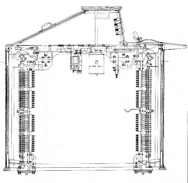
This is a copy of the works diagram for the Westinghouse miniature power lever frame. This is a cross section view which shows the operating lever at the top left of the diagram The two vertical columns left and right are the electrical contacts, which support the electrical lever locking mechanism. The electrical lock are below the frame casting in the center of the picture. Reproduced by kind permission of © John Francis.