The Joys, Delights and Mysteries of Fabrication
Or Great Results Without Tears! From a newsletter article by Jerry Burchell.
Not having the facility of my own home workshop I make good use of the club's workshop, and now as my project – an LMS (Ivatt) Class 2MT tank locomotive in 7¼" gauge is getting rather heavy it is now resident in the club workshop. Many thanks must go to The Workshop Group for their permission!
Many of you have seen the loco. growing and I been in receipt of many kind comments about the fabrications and the level of detail achieved. Some have asked about the techniques I have used, and so my friend here are some jottings, musings and hopefully some useful illustrations.
An Introduction.
Early on during the construction my direction changed somewhat. I had originally intended a relatively simplified design – correct external appearance with a simplified yet robust chassis. However, one fateful Friday evening, Bill Jardin appeared with an interesting looking bundle of plans. "Here," says he, "you're building one of these aren't you? You might want to borrow them for a while".
The interesting bundle turned out to be a set of the reproductions of the General Arrangement plans from the National Railway Museum, and interesting they most certainly were still are!
This was the spur that set me off in the direction of building to greater detail, internally as well as externally. Yes – it's doubled the work but I enjoy the process of design and building.
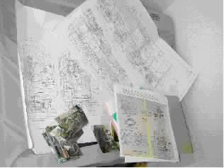
NRM Prints, Plans and Photos.
A part of an Interesting Bundle!
What's this I hear? Designing as well as building? 'Fraid so. I very quickly found out that no plans were available at the level of detail that I wanted to build to and so had to set about preparing my own.
My experience with Computer Aided Design (CAD) came in more than handy, and it has to be said that drawing loco. bits is far more interesting than drawing buildings which is a part of what I do for a living. Perhaps, if you be interested I shall put together a few jottings on translating NRM microfilm prints into useful drawings.
It soon became apparent that I am ploughing a lone furrow here, as no drawings available means no readily available castings. And so it was, gentle reader, that the decision to fabricate parts was made.
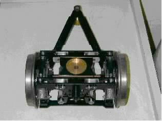
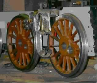
Front Pony Truck. The only castings being the wheels.
Materials, and a Bit of Theory.
Er, sorry about this bit. Be not afraid for 'tis simple and it's all rather interesting really;
The choice of material is very much up to you as the builder. Strength is not really an issue as our dear old friend 'Square-Cube Law' comes to our rescue in our scales. If you build to exact scale (materials and thickness, etc), then the mass of your model diminishes as the cube of the scale, and the area of any part diminishes as the square of the scale.
This has the beneficial effect (in this instance) that the stress on a given part reduces more than significantly!
As an example, take a model built in 1/8th scale: The areas reduce by 1/8th x 1/8th, Giving 1/64th full size area.
The masses reduce by 1/8th x 1/8th x 1/8th, giving 1/512th full size mass. So the stress in a given part will be 1/64 ¸ 1/512, giving 1/8th the full size stress. So! Stress reduces in the same ratio as the scale.
Try it in 1/12th scale or 1/16th scale; whatever you fancy and you will see that the smaller the scale the less significant stress becomes. Not the truth, the whole truth and nothing' but the truth, for other factors come into play.
Firstly our dead scale model will not be very robust. A smashing glass-case miniature, yes. But lacking in strength.
Secondly if you're building to run, shock loadings become much more significant. A minor derailment or running into the bloke in front or even the apparently innocuous running over the frog-gap at every point puts a proportionately greater load on the model. I haven't worked it out, but I wouldn't mind betting that shock, or dynamic loadings are proportionately greater and this would be primarily due to running at over-scale speeds.
Ah! A voice from the back says 'awright cleverclogs worry about boilers, eh'. Quite right. Don't even think about applying this logic to your loco's boiler. It's a pressure vessel subject to a whole different range of considerations.
So what's all this rambling I hear the cry! Ah yes – we were talking about the materials to use. Basically our choice will come down to steel or brass (or a combination), or whatever other similar material comes to hand.
Remember we're talking about load-bearing parts of the model here, so wood and plastics may not be suitable. Unless that is, someone out there knows different! As I am modelling in 7¼" gauge at 1.54":1ft, I have mostly used 1/8" thick steel for my fabrications, and we shall see why.......
A Good Solid Job.
Hot metal and silver solder are great servants but lousy governors. Given the slightest opportunity they will conspire together to shift around, but only during the soldering process resulting in a misshapen sculpture (?). A heinous crime perpetrated by villainous previously inanimate objects, compounded by the hapless human on t'other end of the brazing torch uttering much horrid rudeness upon the realisation of the error of his ways and the un-doing of much good work. Ho-hum.
So! How then to avert the terrible plot?
I have tried several ways with varying degrees of success, so here follows some extracts from my learning curve.
Gentle reader – may it be that it makes your learning curve a little less steep!
Bondage? A.K.A. Iron Tying Wire.
When I first tried silver soldering more years ago than I care to remember I was taught to hold the bits together with loops of soft iron wire.
It certainly works for simple fabrications – say two pieces, but it seems that the propensity for mutual wriggling about under the torch (sounds dreadfully rude that does!) seems to increase by at least the cube of the number of parts. Trust me – I'm a Model Engineer and I tried it. Got into big trouble too!
Basically the trick is to place the wire where it can really hold the (two) parts in close communion, and to twist the ends of the wire together sufficient to achieve that but not so tight that things are encouraged to move around. You can cut off excess wire before soldering; one or two twists at most will do all the necessary and won't get in the way of your stick of solder.
Advantages? Dirt cheap.
Disadvantages? Don't get too clever.
Nail It Together.
WHAT! Outrage! Has the lad gone completely bonkers?!
No! Honest! Not this time!
Panel pins are the trick here. The technique is to pin the parts together with the humble panel pin – available in your local DIY store – and to make sure that the pins are not parallel with each other so the assembly becomes self-supporting and self locking.
As each batch of pins seems to come out a different diameter, check yours with a mike and use the number drill size that provides a nice fit for the pin. It should be a tight push fit without any slop.
If a pin's fit is a bit loose, being made of soft steel a doink with a hammer may seat it satisfactorily, or you can even bend the pin over if desperation arises!
Your assembly will look like a genetically modified hedgehog crossed with something out of Robot Wars. Be ye not afeared for after the soldering process you simply cut and file off the offending projections to end up with a thing to be much admired.
Advantages? Fairly cheap.
Disadvantages? None really, but needs practise.
Back to Woodworking Lessons.
If you're not into woodwork, perhaps you remember the lessons you had at school? Mortise and tenon joints ring any bells? What about cross-halving joints?
Use the same methods in miniature to joint your pieces together. Think it through carefully, particularly where several parts are to be assembled. It's quite easy with a little practise to achieve a good fitting self-supporting assembly that won't move during brazing.
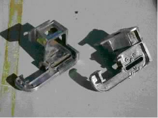 Weighshaft Brackets before soldering.
The internal flanges are cross-halved to the web plate. The external flanges and mounting plate are held by 8BA screws.
It is important to make sure that the meeting faces of the separate parts are truly square (in both directions by the way), so that the assembly assembles properly square.
Advantages? Dirt cheap.
Disadvantages? Needs good filing technique, but you've got that already!
Screwing It Up.
My favourite! No doubt about it!
Oh yes indeedy!
Here, the parts are simply held in place with a screw a series of screws. The picture above shows the external flanges being taught good sense by 8BA countersunk head screws. In this case, only one screw each holds the flanges and the mounting plate – 3 screws in total.
It's important that the clearance hole in one part and the tapped hole in t'other are truly axial so's to end up with a satisfactory assembly.
An early mistake of mine was to drill the tapping hole to give the usual 65% engagement. Big mistake. Very silly. A bit of good advice (probably after having broken another tap) was to drill a larger diameter as once the soldering is completed, the screw has done its job and performs no structural function. Ah! Clarity is a wonderful thing, and it seems, born of 20/20 hindsight. So for example, now I use a no48 drill for 8BA threads. Result? Easy-peasy tapping, no broken taps, and bits firmly held.
Advantages? Suitable for complex assemblies.
Disadvantages?
Needs good filing technique, but you've got that already! And the cost of the screws? Needs careful fitting together.
This and That and Both and All.
Meaning......
You don't have to use just one method for your particular job. Any combination can be made to work – it all depends on the job in hand. Also, you will soon find your favourite method. The motion brackets in the following picture used all four methods that I've described.
MOTION PLATES
My most complicated fabrication yet.
It used all of the described holding methods.
Last But Not Least....
Best practise, as ever makes perfect. But not too perfect mind! Your bits must be square if that's what the job demands, or filed/machined to the correct angles. However don't forget that the silver solder likes a little gap to run through, thus to make the perfect joint – strong and a delight to behold. If necessary, file little nicks with a square or triangular file to create a path for the solder to find its way through.
Silver Soldering.
Oh I know! It holds many horrors for some, and seems a great mystery to others. Stories abound of expensive failures and all sorts of nasties, but believe me, t'aint so bad.
True, things have gone wrong on and off, but so far I've found out for why. And it all comes down to a few simple rules that anyone who wants to have a go can follow AND win success But! Domestic duties call and if there be interest, I'll hap'ly pen a page or two.
Come and have a chat.
TTFN.
Jerry Burchell