The Roundhouse Journal June 2000
Welcome to the Spring edition of the Roundhouse Journal, may I wish you all a belated Happy Easter and an enjoyable Bank Holiday break or two. I hope you all are able to enjoy this new steamy (as in steam and smoke!) Season.
I can also report that as usual considerable activity is still taking place at the club site, work is progressing on several fronts simultaneously.
The new central heating system has been installed, so were all nice and warm, and the kitchen and toilets have lashings of hot water. I must publicly thank John Mottram for a huge amount of work that he did free of charge including getting a small team of members doing little jobs like boarding out the roof, no small task in its self. Johns the team also drilling holes in walls, screwing up lots of radiators, built protective wooden boxes for pipes in the roof space, they ran electric cables to where they were needed. Fortunately (or unfortunately depending on your point of view) nearly all the work is hidden from view so most people will never know how much work went into this project.
The 7¼ ground level track renewal in Willowbank station is now nearly completed 1 week before Easter, though we will have to wait till May / June for the rest of the 3 new points to be installed and operations.
The raised track rolling stock passenger cars have now all received their modifications to allow our younger passengers to be carried, again this has been another sub project in its own right, with a dedicated team beevering away. At least there will no longer be an age restriction on the raised track. Well done guys.
Whilst the raised track cars were being modernised the team also managed to replace several concrete beams on the raised track adding super-elevation with a concrete skim.
If that wasn't enough a huge effort is being put into some really serious earth works and concrete blocking to retain the earth on the 7¼ ground level line to allow the 'Alps line' to be put into operation next year. This will allow more trains and remove the last real single-line bottleneck. One wall of the new tunnel is now 40% complete and the second wall footings are being set.
All in all there is a regular Sunday working group of not less that 15 people every Sunday. Just recently 23 sat down for Sunday lunch at the club. (Soup, bread cheese, sandwiches, bring your own etc. ) Numbers also swell up in the afternoon as extra people come to use the workshop facilities for their own engineering projects.
I'm glad to add that Peter Larkin is down again keeping us all on our toes on Sundays following his recovery from his op.
So all in all the club appears very active which to my mind is what it is all about. Friday nights are also proving popular. John Mottram our Social Sec and Eric Offen gave us another brilliant evening again by arranging to for Mike Murphy from the Model Gas turbine Association to give a second talk on his miniature turbines, which amongst other achievements has now been fitted into a model helicopter which has flown successfully. It was a very interesting talk, especially as it was very clear the amount of progress in 18 months since the last talk / demonstration.
For more information about the Model Gas Turbine Association please contact Eric or John or see MGTA web site located at:
Further Friday evening specials details will be posted by mail shot or at the back of this newsletter.
In closing this editorial may I suggest that if your at a loose end any Sunday don't forget, there's always a welcome for you at Thames Ditton. Please also remember that we do need you on track days to run the railway for the public.
And remember there's always friendship & camaraderie and the water urn is always on to make the tea or coffee. So we hope top see you there soon.
Mark Adlington,
Editor
HSE Draft document
Following the distribution of the Health and Safety Executives "Model Engineering: Guidance on the safe operation of miniature railways and model traction engines" in the last newsletter. We have now received further communication which is contained later on in this newsletter.
Committee
A Personal Perspective on the International Model Exhibition 1999.
Sorry this didn't get in the last news letter, but copy arrived too late to include .
Most of you I know will at least have seen advertisements in the model engineering press for the IMS at Ally Pally last December. As usual, the club had a stand provided by the exhibition organisers and it fell to my lot together with Eric Offen to manage our stand this year. So I thought to pen a few words about the event for those of you who were unable to attend.
The Venue
The Alexandra Palace is new to me as an exhibitor, and I was pleased to find a very good venue, with a good stand size provided for us; 10 x 20 feet, and nice wide aisles between stands to allow visitors plenty of room to circulate or chat as is their want. The downside is that for us south London dwellers, it's horrible to get to! At least there's plenty of free car parking!
The Club Stand
Our stand has seen many years good service and was getting a bit tatty around the edges. The ministrations of time, repeated sets-up and stripping down and loft dwelling squirrels had taken their toll. A recovering was definitely in order! Thanks here to Mark Adlington for taking time out to purchase the material – a good choice of colour that everyone approved of, and to Dave and Elizabeth Wilkins for the many hours spent in recovering the stands. A really neat job done that spruced up the stands no end!
Setting Up
Setting up day dawned nice and early with a merry squawk from the alarm clock and a groan from me. Up and away I go to open up the club-house for a 9.00AM start. Kettle on – there are priorities! – and soon the rest of the setting up team and models started to arrive. Once we could see how much of what we had to pack, van and car springs started to creak as we loaded up. Always a bit of a tedious job this one, with much care taken to ensure the models arrived at the exhibition in good shape.
It's a good hour-and-half's journey from the club to Ally Pally, and so it was that your intrepid team arrived without incident (I won't mention the traffic for some strange game at Twickenham) and were soon unpacking ready to set up the stand. A quick reconnaissance located our stand's whereabouts and instructions received from the security staff on unloading and parking procedures. Why do security staff always seem so harassed and authoritarian? Must take years of training!! The set-up itself proceeded without any great problems, and soon a good show was put together ready for the morrow.
Let the Show Begin!
And so the morrow arrived with an even earlier merry squawk and groan. The show opened at 9.30AM each day with exhibitors admitted from 8.00AM. So getting there in good time meant arising at 5.30AM most days – AARGH! Horrendous! Ah well, duty calls!
I soon had a routine established; first things first and the kettle goes on and whilst its boiling I can check around the stand making sure that all is as it should be. Tea ready and I start dusting round – must have the models looking good! If I'm lucky I get the chance of a quick look round the other stands before the public are admitted.
Once the team has assembled, we agree a rota that allows us all time to look around the show, go to the restaurant, buy our stock materials and tooling, chat to friends on other stands, and – oh yes! Mustn't forget – look after the club stand!
The Exhibition Itself
I enjoyed the show, all six days of it! As with all exhibitions of this nature covering as they do a wide range of activities, there were some things that left me cold. There were others, by far the greater majority, which caught my interest. There were still others that absorbed me totally and were absolutely inspirational! Marvellous stuff! As you might guess, for me there was plenty to see and enjoy and spend time with.
One of the great pleasures is to renew old acquaintances and meet new kindred spirits. Many were the enjoyable conversations had with others with similar interests to my own, often with an exchange of information and telephone numbers for planned collaboration on projects.
It is also gratifying to be able to tell a visitor about one of the exhibits, perhaps something of its history and how long it took to build, perhaps how it works – I really must get to grips with the Stirling Engine cycle, an explanation including 'Magic liberally dosed with Perpetual Motion' is none-too-technical!
To be able to direct an enquirer to similar exhibits on other club stands in reciprocation is a sure sign of good camaraderie between clubs – no bad thing that, says I!
Stripping
Paint? Naughty ladies or The Chipmunks? No, not at this exhibition! All good things come to an end; so it was with the show and all had to be packed away and transported back to the club-house. We were not permitted to start dismantling until all the public had left the building, and then what a race! Eric whizzed off with the intention of parking his van as close to the loading bay at the back of Ally Pally as he could. Struck gold too! He couldn't have parked more conveniently if he tried!
The rest of us in the meantime seemed to be in competition with the contractors dismantling the stands themselves – fluorescent lights and power points were simply ripped off the stand framework and the power cabling and conduits snipped through with wire cutters! We concluded they were on contract to clear the halls by midnight – they certainly weren't hanging around for anybody!!
And so all our exhibits were again carefully stowed and a long journey back through the legendary North Circular Car Parking Facility went with little incident but much tedium.
And So To The Future
It was a good exhibition at a good venue, definitely an improvement on last year. It seemed to be well patronised on all days and in particular the weekend when many families attended. There are some thoughts in the air to improving the club's display stands; I have noticed a definite upgrade in the standard of club displays in recent years and it would be great for our club to stand out even more with a really smashing display. Has anybody any ideas that don't involve too much expense or labour?
Of course, no display is complete without exhibits and here I would like to thank all those who generously loaned exhibits this year. To be able to show a wide variety of our work, whether complete or partially complete makes an engaging display and does attract interest from the public. By the way, don't be shy about standard of workmanship, people love to see 'perfection', they also appreciate seeing models built to a standard they too can achieve. You're proud of what you have achieved I'm sure; show it off!!
I would also like to say a huge thank you to all of you who assisted so ably in setting-up, breaking-down and stewarding the stand. All of your efforts are greatly appreciated and the show could not have been done without you. Many, many thanks.
And so to conclude;
Do I enjoy mucking in at the IMS - Yes.
Is it hard work? Oh yes.
Is it worth it? Oh very yes.
See you there next time, and don't forget to bring forth your produce!
TTFN. Jerry Burchell.
Safety - Nails and Wood
The committee was recently distressed to hear of an injury resulting from a member stepping on a nail protruding from a piece of wood. It is always desirable to wear adequate protective footwear on a working site like our club's. However we must remain aware that this footwear is often not available in small sizes for children, and that visitors may be conducted around the site. Please can everyone take a personal role in the reduction of this safety risk. In particular, please: -
* If you are dismantling a wooden assembly on-site, it is your personal responsibility for making the parts safe straight away - please don't leave the job for others or until some time later at the end - in case later (like tomorrow) never comes. If the wood is destined for scrap, people can still be injured during a tea break so at least spend a moment to bend over the nails so they will not penetrate hands and feet.
* Please do not bring onto the site any wood with nails in (or with wood-worm or rot for that matter) - unless you have made a specific arrangement in advance with someone to deal with the risk immediately upon arrival.
We do have an on-going need for scrap wood particularly for track sleepers.
The minimum dimension for this 2x2" (or 47mm as sawn in these metric days) and 14 1/2" or 370 mm long. We can cut up larger sizes. A regular supply of this wood saves the club a substantial amount of money, and we are indebted to several members who have recently made donations of scrap building timbers for this purpose.
Other timber, planking and boarding may well be of use to us, but please check with a member of the committee before bringing it down. Because we have a regular supply of off-cuts from cutting up timbers for sleepers, we do not need wood scraps for steaming up purposes.
Martin Baker
Holmside Model Engineering Society
Originally The JAMES BURN International model Engineering Society was formed in 1980 by the then Managing director Garth Allen and a few keen railway enthusiasts.
With help from the company the first engine and two carriages were obtained. The engine was a 'Holmside' 0-6-0 Pannier Tank engine purchased from Mr. Ron Martin of Bristol, coal fired with a working steam pressure of 100lbs/sq in. Scaled to run on a 7¼" track. Approximately 200ft of track in 6ft lengths was constructed by the members.
In the early years the company allowed the use of one of the company lorries and driver to transport all the equipment to the various charity functions. In 1987 the society was able to purchase it's own van which enable us to leave everything loaded until the next event thus cutting out a lot of loading and unloading on the day.
Up until the 1990's the society flourished with up to twenty members but in all cases good times had to end and due to a number of factors the membership fell until only a hard core were left. In 1991 after years of loyal service and much hard work on the part of "James Burn" and the members, keeping it running in all weathers "JAMES" was retired and a replacement engine was purchased again from Mr Ron Martin identical to he first and now carries the same name.
Over the years good and bad we have enjoyed our involvement at both large and small fetes and have raised over £6000 in donations to various charities. This has been done with no small help and advice from the members of The MALDEN AND DISTRICT SOCIETY OF MODEL ENGINEERS.
We have now arrived at a crossroads for our group. With major changes taking place and our membership at its lowest level ever, it was suggested by the company that we divorced ourselves from it, and try to integrate into some other society. We are extremely pleased to say that true to form Malden and District Society of Model Engineers has offered to consider our small group for membership.
Looking to the future we hope to be able to show our appreciation for the assistance and help we received over the years.
New Members
We welcome the following new members, Sidney Stiles, Paul Gammon, Brian Horder, Derek Deeks, Gavin Sapsed, Dennis Sapsed
The Joys, Delights and Mysteries of Fabrication
Or Great Results Without Tears! From a newsletter article by Jerry Burchell.
Not having the facility of my own home workshop I make good use of the club's workshop, and now as my project – an LMS (Ivatt) Class 2MT tank locomotive in 7¼" gauge is getting rather heavy it is now resident in the club workshop. Many thanks must go to The Workshop Group for their permission!
Many of you have seen the loco. growing and I been in receipt of many kind comments about the fabrications and the level of detail achieved. Some have asked about the techniques I have used, and so my friend here are some jottings, musings and hopefully some useful illustrations.
An Introduction.
Early on during the construction my direction changed somewhat. I had originally intended a relatively simplified design – correct external appearance with a simplified yet robust chassis. However, one fateful Friday evening, Bill Jardin appeared with an interesting looking bundle of plans. "Here," says he, "you're building one of these aren't you? You might want to borrow them for a while".
The interesting bundle turned out to be a set of the reproductions of the General Arrangement plans from the National Railway Museum, and interesting they most certainly were still are!
This was the spur that set me off in the direction of building to greater detail, internally as well as externally. Yes – it's doubled the work but I enjoy the process of design and building.
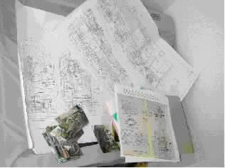
NRM Prints, Plans and Photos.
A part of an Interesting Bundle! What's this I hear? Designing as well as building? 'Fraid so. I very quickly found out that no plans were available at the level of detail that I wanted to build to and so had to set about preparing my own.
My experience with Computer Aided Design (CAD) came in more than handy, and it has to be said that drawing loco. bits is far more interesting than drawing buildings which is a part of what I do for a living. Perhaps, if you be interested I shall put together a few jottings on translating NRM microfilm prints into useful drawings.
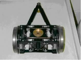
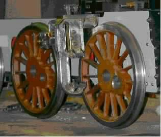
Front Pony Truck. The only castings being the wheels. Materials, and a Bit of Theory.
Er, sorry about this bit. Be not afraid for 'tis simple and it's all rather interesting really;
The choice of material is very much up to you as the builder. Strength is not really an issue as our dear old friend 'Square-Cube Law' comes to our rescue in our scales. If you build to exact scale (materials and thickness, etc), then the mass of your model diminishes as the cube of the scale, and the area of any part diminishes as the square of the scale. This has the beneficial effect (in this instance) that the stress on a given part reduces more than significantly!
As an example, take a model built in 1/8th scale: The areas reduce by 1/8th x 1/8th, Giving 1/64th full size area.
The masses reduce by 1/8th x 1/8th x 1/8th, giving 1/512th full size mass.
So the stress in a given part will be 1/64 ¸ 1/512, giving 1/8th the full size stress.
So! Stress reduces in the same ratio as the scale.
Try it in 1/12th scale or 1/16th scale; whatever you fancy and you will see that the smaller the scale the less significant stress becomes. Not the truth, the whole truth and nothing' but the truth, for other factors come into play.
Firstly our dead scale model will not be very robust. A smashing glass-case miniature, yes. But lacking in strength.
Secondly if you're building to run, shock loadings become much more significant. A minor derailment or running into the bloke in front or even the apparently innocuous running over the frog-gap at every point puts a proportionately greater load on the model. I haven't worked it out, but I wouldn't mind betting that shock, or dynamic loadings are proportionately greater and this would be primarily due to running at over-scale speeds.
Fabricated Motion Plate
So it is that it makes goodly sense to beef up parts a little. Not a little, just a little. It has become customary amongst designers to allow an 'overscale factor' of some 25-30% to allow for these factors.
Ah! A voice from the back says 'awright cleverclogs worry about boilers, eh'. Quite right. Don't even think about applying this logic to your loco's boiler. It's a pressure vessel subject to a whole different range of considerations.
So what's all this rambling I hear the cry! Ah yes – we were talking about the materials to use. Basically our choice will come down to steel or brass (or a combination), or whatever other similar material comes to hand.
A Good Solid Job.
Hot metal and silver solder are great servants but lousy governors. Given the slightest opportunity they will conspire together to shift around, but only during the soldering process resulting in a misshapen sculpture (?). A heinous crime perpetrated by villainous previously inanimate objects, compounded by the hapless human on t'other end of the brazing torch uttering much horrid rudeness upon the realisation of the error of his ways and the un-doing of much good work. Ho-hum.
So! How then to avert the terrible plot?
I have tried several ways with varying degrees of success, so here follows some extracts from my learning curve.
Gentle reader – may it be that it makes your learning curve a little less steep!
Bondage? A.K.A. Iron Tying Wire.
When I first tried silver soldering more years ago than I care to remember I was taught to hold the bits together with loops of soft iron wire.
It certainly works for simple fabrications – say two pieces, but it seems that the propensity for mutual wriggling about under the torch (sounds dreadfully rude that does!) seems to increase by at least the cube of the number of parts. Trust me – I'm a Model Engineer and I tried it. Got into big trouble too!
Basically the trick is to place the wire where it can really hold the (two) parts in close communion, and to twist the ends of the wire together sufficient to achieve that but not so tight that things are encouraged to move around. You can cut off excess wire before soldering; one or two twists at most will do all the necessary and won't get in the way of your stick of solder.
Advantages? Dirt cheap.
Disadvantages? Don't get too clever.
Nail It Together.
WHAT! Outrage! Has the lad gone completely bonkers?!
No! Honest! Not this time!
Panel pins are the trick here. The technique is to pin the parts together with the humble panel pin – available in your local DIY store – and to make sure that the pins are not parallel with each other so the assembly becomes self-supporting and self locking.
As each batch of pins seems to come out a different diameter, check yours with a mike and use the number drill size that provides a nice fit for the pin. It should be a tight push fit without any slop.
If a pin's fit is a bit loose, being made of soft steel a doink with a hammer may seat it satisfactorily, or you can even bend the pin over if desperation arises!
Your assembly will look like a genetically modified hedgehog crossed with something out of Robot Wars. Be ye not afeared for after the soldering process you simply cut and file off the offending projections to end up with a thing to be much admired.
Advantages? Fairly cheap.
Disadvantages? None really, but needs practise.
Back to Woodworking Lessons.
If you're not into woodwork, perhaps you remember the lessons you had at school? Mortise and tenon joints ring any bells? What about cross-halving joints?
Use the same methods in miniature to joint your pieces together. Think it through carefully, particularly where several parts are to be assembled. It's quite easy with a little practice to achieve a good fitting self-supporting assembly that won't move during brazing.
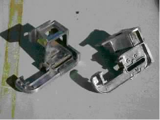
Weigh shaft Brackets before soldering.
The internal flanges are cross-halved to the web plate. The external flanges and mounting plate are held by 8BA screws.
It is important to make sure that the meeting faces of the separate parts are truly square (in both directions by the way), so that the assembly assembles properly square.
Advantages? Dirt cheap.
Disadvantages? Needs good filing technique, but you've got that already!
Screwing It Up.
My favorite! No doubt about it!
Oh yes indeedy!
Here, the parts are simply held in place with a screw a series of screws. The picture above shows the external flanges being taught good sense by 8BA countersunk head screws. In this case, only one screw each holds the flanges and the mounting plate – 3 screws in total.
It's important that the clearance hole in one part and the tapped hole in t'other are truly axial so's to end up with a satisfactory assembly.
An early mistake of mine was to drill the tapping hole to give the usual 65% engagement. Big mistake. Very silly. A bit of good advice (probably after having broken another tap) was to drill a larger diameter as once the soldering is completed, the screw has done its job and performs no structural function. Ah! Clarity is a wonderful thing, and it seems, born of 20/20 hindsight. So for example, now I use a no48 drill for 8BA threads. Result? Easy-peasy tapping, no broken taps, and bits firmly held.
Advantages? Suitable for complex assemblies.
Disadvantages?
Needs good filing technique, but you've got that already! And the cost of the screws? Needs careful fitting together.
This and That and Both and All.
Meaning......
You don't have to use just one method for your particular job. Any combination can be made to work – it all depends on the job in hand. Also, you will soon find your favorite method. The motion brackets in the following picture used all four methods that I've described.
MOTION PLATES
My most complicated fabrication yet.
It used all of the described holding methods.
Last But Not Least....
Best practice, as ever makes perfect. But not too perfect mind! Your bits must be square if that's what the job demands, or filed/machined to the correct angles. However don't forget that the silver solder likes a little gap to run through, thus to make the perfect joint – strong and a delight to behold. If necessary, file little nicks with a square or triangular file to create a path for the solder to find its way through.
Silver Soldering.
Oh I know! It holds many horrors for some, and seems a great mystery to others. Stories abound of expensive failures and all sorts of nasties, but believe me, t'aint so bad.
True, things have gone wrong on and off, but so far I've found out for why. And it all comes down to a few simple rules that anyone who wants to have a go can follow AND win success But! Domestic duties call and if there be interest, I'll hap'ly pen a page or two.
Come and have a chat.
TTFN.
Jerry Burchell
Since the earlier entry we welcome even more new members, we welcome
George Evenden, Barrie Ryan, Iain Leitch, Jennifer Mottram (formerly a junior member)
Junior Associates: Andrew Needle, Timmy Noble
From the Southern Federation.. For Your Info
Health and Safety - Safe operation of miniature railways, traction engines and road vehicles.
The document has finally been approved and is with the printers. Previously referred to as 'the model engineering guidance this document is now to be published by the HSE in its Information Sheet series (Entertainment Sheet No12). It is aimed at model engineers, as individuals or under the patronage of a club/society, operating models as a hobby activity in a public place, particularly those able to give rides Contributions from the model engineering fraternity helped considerably in compiling the final version.
Copies will be available around the middle of June and will be dispatched, by the national organisations, to all affiliated clubs as soon as possible thereafter. Sufficient copies will be made available to clubs, to enable distribution to every member.
Technical Note 3 - its replacement and the consultation procedure.
TN3 eventually will be replaced by a document entitled Passenger Carrying Miniature Railways; Guidance on Safe operation and as it says in its title is specific to the operation of miniature railways (both private and commercial). The Miniature Railway Liaison Group, on which the SFed has representation, has been involved with the drafting of the proposed document and it is almost at the stage when it can be released as a consultation document. Less specific than previous it will be required reading for anyone operating a miniature railway. Now is your chance to have a say in its formulation - the HSE is prepared to listen!
As it is a somewhat lengthy document ;It has been decided That copies will be available only on request. Copies will be available in June and you may obtain a copy by sending your name and address to Dr T Williams, Health and Safety Executive, 375 West George Street, Glasgow G2 4LW. Anyone is free to take part in the consultation process but note that all comments will have to be returned by 31st August 2000. We request that anyone commenting on the document should also send a copy of their comments to the SFed's representative on the M RLG - Mike Leahy, 9 Poplar Close, South Ockendon, Essex. RM. 1 5 BTU.
Road Traffic Act Insurance.
The law relating to the insurance of motor vehicles has recently changed - Motor Vehicles (Compulsory Insurance) Regulations 2000 of the 3rd April 2000. Whereas, before, the requirement was for "a motor vehicle on the road to be covered by an appropriate policy of insurance" the wording has been altered so that after "road" there shall be inserted "or other public place". Unfortunately this applies also to the use of miniature traction engines, miniature road rollers and miniature road vehicles and therefore it is mandatory that you have the relevant Insurance to drive such vehicles on off-road locations, private land, rally fields, etc., where the public may have access.
The policy extension that is available to individual members, whose clubs have Third Party Insurance, is insufficient for this purpose and so the Fed has arranged with our insurers a Model Steam Road Policy which provides suitable cover. It covers vehicles of up to 6' scale and also is available to owners of miniature road vehicles powered by means other than steam.
The policyholder or any person driving with his permission are covered but if miniature vehicles are driven on the road, the driver must be aged 17 years or over, a category B driving licence must be held and it may be necessary that the vehicle is suitably registered for use on the road. For driving on 'off-road' locations the driver must be aged 16 years or over.
Cost is £31. 50 per vehicle for third party cover and for an additional sum (according to value of the model) Comprehensive Cover may be obtained.
All clubs have been circulated with an insurance package which fully explains the details but we find that many individual club members are still unaware of the situation. Therefore, we ask club officers to ensure that your members are fully briefed on the situation. A suitable notice, outlining the policy, was included in the package which could be displayed on your club notice board. Club officers are also reminded that when submitting the application form for such insurance (Form F7) they must have sight of relevant documents/information and the form be completed before countersigning the application.
Any club organising an event, rally or Open-Day, where the public may be present, should check that all participating miniature road vehicles have the relevant insurance before being allowed to run.
If you wish to operate a miniature road vehicle at a rally organised by the NET it is a requirement that you have a disc affixed to the vehicle that shows that the vehicle is covered by RAT Insurance and such discs will be issued to all policyholders by the Fed Insurance Administrator, End McGhie.
Dear Member -
Your practical hands on help is needed in helping to run this Society.
If everybody does just a little something to help with the maintenance activities for just one or two Sunday afternoon a year a lot of things can be done and achieved.
(other days can also be arranged)
More help on our public Open days would greatly help
Us run a smoother operation as there would be more people to spread the load, there are numerous choices of activity.
Please contact any committee member
For more info
Don't be afraid we won't / don't bite
June 2000